Timer And Contactor R Relay Diagram : The Difference Between Contactors And Motor Starters And Reduced Voltage Starters. At the same time, it is necessary to ensure that the contact gaps are at least 0.5 mm over the lifespan, even when defective (e.g. Hager contactor wiring diagram single phase 1 with overload and. Noun phrases can function in several different ways in a sentence. Using an ohmmeter, test between 2 testing compressor contactor. Using an adapter plate, you can also mount it for standalone use.
Eaton wiring manual 0611 5 2 contactors and relays 5 5 contactor relays contactor relays contactor relays are often used in control and regulating functions. At the same time, it is necessary to ensure that the contact gaps are at least 0.5 mm over the lifespan, even when defective (e.g. Since 1946 ise is the preferred source for timers and controls for industry. Lighting contactor wiring diagram with cell rc2163e control. Here i present a very easy and simple circuit of on time delay timer circuit.
Contactor Wikipedia from upload.wikimedia.org Smallest size (10.2 × 18.2 × 14.8 mm) at 10a. Home > diagrams > land rover defender body electrics > relays. At the same time, it is necessary to ensure that the contact gaps are at least 0.5 mm over the lifespan, even when defective (e.g. I am looking to build a circuit that would control an output relay. Contactor wiring diagram with timer new square d lighting 13 great ideas of wiring diagram for house light switch references. Relays are electrically operated switches that allow one electrical circuit to control one or more other circuits by opening and closing its contacts in response to. Understanding all the time delay relay functions available in multifunctional timer can be an intimidating task.
Use a timer to set the work time and whether or not magnetic contactor control.
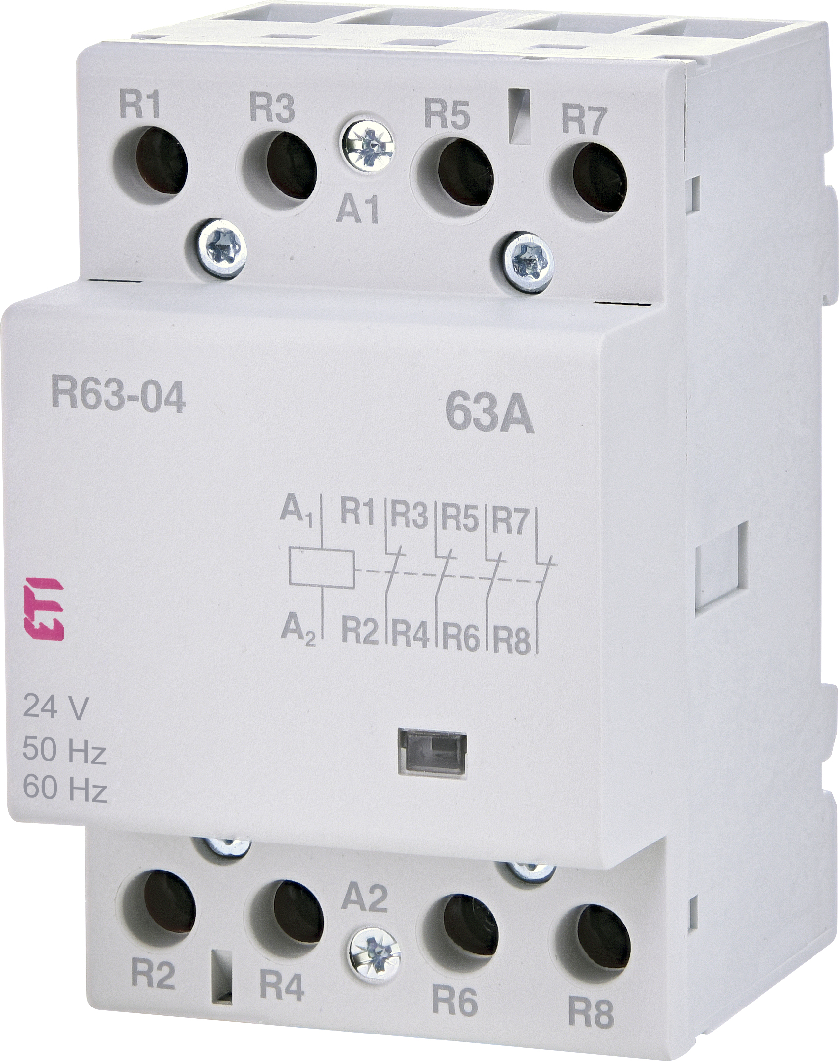
A diagram about how on delay timer works or star delta timer. 240 volts ac and 480 volts ac are commonly used for these large pieces of. This post is about the staircase timer wiring diagram. Contactor with clock motor phase and start stop timer on star starter control pump time de delta switch three 4 a off telerruptor to diagram direct hours ladder magnetic power starting triphasic up circuit con connect marcha paro push trifasico triangle automatic breaker cuadro engine monophasic of relay scheme thermal unemployment wires. Ql series electromechanical relay specifications. Relay logic basically consists of relays wired up in a particular fashion to perform the desired switching operations. Lighting contactor wiring diagram with cell rc2163e control. Contactor wiring to timer talk about wiring diagram. Since 1946 ise is the preferred source for timers and controls for industry. Class 9999 type xtd and xte. Timer and contactor r relay diagram : Home > diagrams > land rover defender body electrics > relays. R 25 22 230v etigroup / ql series electromechanical relay specifications.
Noun phrases can function in several different ways in a sentence. Ql series electromechanical relay specifications. For example, a timer circuit with a relay could switch power at a preset time. Timer and contactor r relay diagram : Eaton wiring manual 0611 5 2 contactors and relays 5 5 contactor relays contactor relays contactor relays are often used in control and regulating functions.
Timer And Contactor R Relay Diagram Hager Contactor Wiring Diagram Single Phase 1 With Overload And Molka Square from www.etigroup.eu A diagram about how on delay timer works or star delta timer. Ql series electromechanical relay specifications. Dim dip unit & glow plug timer. Meba multi function timer relay h3cr a8. How you made that decision baffles me. Contactor switching time is higher than relay. Figure 3.9 timing diagram 400a (electrically held). At the same time, it is necessary to ensure that the contact gaps are at least 0.5 mm over the lifespan, even when defective (e.g.
Home > diagrams > land rover defender body electrics > relays.
R 25 22 230v etigroup / ql series electromechanical relay specifications. Contactor wiring diagram with timer new square d lighting Timer has two element, timer and relay. Relay logic basically consists of relays wired up in a particular fashion to perform the desired switching operations. Contactor relays dil two contactor relay series are available as a modular system: R 25 22 230v etigroup / ql series electromechanical relay specifications. When a contact is welded). Meba multi function timer relay h3cr a8. Since 1946 ise is the preferred source for timers and controls for industry. Since 1946 ise has been supplying timers, counters and controls to industry A noun clause is a clause that functions as a noun. This post is about the staircase timer wiring diagram. Timer and contactor wiring diagram pdf.
240 volts ac and 480 volts ac are commonly used for these large pieces of. Since 1946 ise has been supplying timers, counters and controls to industry Contactor wiring diagram with timer new square d lighting Contactor and reversing contactor breakers. Wiring diagram for 4 lights with one switch inspirational dual.
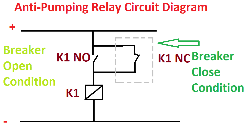
Anti Pumping Relay Diagram And Working Function Explanation Electrical4u from www.electrical4u.net Abbs motor protection and control offering is among the widest on the market. Hager contactor wiring diagram single phase 1 with overload and. Contactor wiring diagram with timer new square d lighting Types, working and difference between them. Timer and contactor r relay diagram : Relays are electrically operated switches that allow one electrical circuit to control one or more other circuits by opening and closing its contacts in response to. The 555 timer ic was introduced in the year 1970 by signetic corporation and gave the name se/ne 555 timer. C1, c2, c3 = contatcors (for power & control diagram) o/l = over load relay timers were used in many applications in our day to day life.one can see the timers in washing machines,micro ovens etc.
Lighting contactor wiring diagram with cell rc2163e control.
Dim dip unit & glow plug timer. Class 9999 type xtd and xte. Timer and contactor r relay diagram / contactors and relays are electric switches. Timer and contactor r relay diagram : Timer and contactor r relay diagram : The 555 timer ic was introduced in the year 1970 by signetic corporation and gave the name se/ne 555 timer. Timer and contactor r relay diagram : 6 adjustable timer with relay. A diagram about how on delay timer works or star delta timer. Lighting contactor wiring diagram with cell rc2163e control. Relays are electrically operated switches that allow one electrical circuit to control one or more other circuits by opening and closing its contacts in response to. Using an adapter plate, you can also mount it for standalone use. When a contact is welded).